So, till now we have configured our environment to use switches and routers that we added here.
Now lets work in a small network that consists some hosts (we will use routers in our topology to refer to hosts). We will refer to this small network as a Local Area Network (LAN).
What is LAN – A LAN can defined as network that covers a smaller area, for example a lab environment, building, or multiple hosts connected together in a confined geographical location. Hosts communicate with each other with the use of unique IP addresses that are a part of the same sub-network (subnet). We will discuss more about IP addresses in a different post.
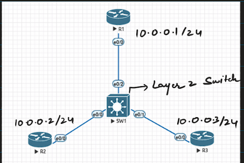
Let us assume a scenario where we have 3 hosts (represented by routers in the topology) R1, R2 and R3, connected together using a layer 2 switch. Hosts have IP address as shown in the image above.
Now lets start, for any kind of communication to occur we need IP, we have assigned those. Now if I ping from R2 to R3, should it work in the first go, yes or no, maybe the first one will take more time to complete, let’s give it a go:
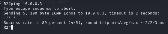
- The first ping does not work, because in order to communicate with the IP address (layer 3 logical address) we also need a next hop mac address (physical address – permanent).
- In this case our hosts knows that it’s destination is in the same subnet, so it needs the MAC address of the host with IP address – 10.0.0.3/24.
- To grab that it sends out an ARP (Address Resolution Protocols – will be discussed in another article) request. This protocol is used to fetch the MAC address associated with the IP address that we are trying to reach (if the destination IP is in the same network, otherwise the request is sent to fetch the MAC address of the next hop, which will be the gateway in case the IP address belongs to another network.
- The ARP request sent will be a layer 2 broadcast and the reply will be a layer 2 unicast. the same can be seen in the wire shark capture below:

- The reason for the request being a broadcast is because it does not know who the intended receiver is, that is why it should reach all the possible hosts/candidates on that network – just like at an appointment, when they call out your name everyone in the lobby hears it (broadcast request), but only you (the intended target) respond to it (unicast reply.)
- This ARP request/reply that were generated gave R3 the MAC address associated with R2 (R3 got to know this when processing the Broadcast request – because it was the target ip address) and also gave R2 the MAC address associated with R3 to initiate the communication.
This is just an overview of how the ping is successful. There is one more thing that took place during this ping conversation between hosts R2 and R3. We see there is a switch connecting all the hosts in the network. That switch also needs to process the incoming frame in order to decide how it should be handled. Here I will try to discuss how the switch SW1 works here:
- Most of the times a switch is used to connect different hosts in LAN together, so that they can communicate with each other, each host is connected to a port on a switch.
- As we all know switches work at layer 2, they use MAC address to decide where to forward the frame to.
- A switch maintains a MAC address table where maps MAC address to ports to which that specific host is connected to.
- So, how does a switch know about these MAC address, and what if the MAC address table is empty at the begining.
- Lets got back to the ping example where we sent an ARP request before initiating any IP based communication.
- Now the switch has no entry in the table, it receives a broadcast frame from host R2 on port e0/0, that frame will have a source MAC address of R2 and a destination MAC address of ff:ff:ff:ff:ff:ff (which represents broadcast).
- To make an entry in the table, switch always uses a the source mac address from a frame, the reason for this is that the host with source mac address will always be there in the network, but a destination may or may not be present.
- Now as the switch has analyzed the frame, it will do an entry for that mac address, the port from which it can in and the vlan (Virtual Local Area Network) the vlan the port is associated to (by default all the ports are a part of vlan 1 – native vlan).
- Now to process it further, the switch looks at the destination MAC address (for forwarding purposes), in this case the destination is layer 2 broadcast address (ff:ff:ff:ff:ff:ff), so it will forward it to all the ports except the one it received the frame on.
- Here, the destination MAC was a broadcast itself, so it was treated that way, what if we had a unicast MAC address in the destination field. The switch will first to a lookup in the MAC address table. If it finds a corresponding entry, it will forward the frame to the mapped port, and if there is no matching entry in the MAC table, then the switch forward the frame out of interfaces except the one it received the frame on – i.e., it will treat that as broadcast, because it does not know where the intended target is located
This is all for now, If you guys have any question regarding, even the topics that we have not discussed here, feel free to ask them below.
And you are more than welcome to leave a feedback for the article or point out there is any mistake or something missing.
2 responses to “At Layer 2 – Switching”
Superb explanation sir.
Thank you 🙂